The wiring methods of rectifier bridge [ASEMI]
Return ListSource:Asemi Date:2009.12.31 Read:0
of rectifier
bridge【ASEMI】
Do you know the wiring method of rectifier bridge ? I believe that many people have such problems about how to connect and apply. Now follow the introduction of the ASEMI engineer for more details , let’s go !
Learn to judge the "+" and " - ” firstly
The rectifier bridge is a widely used type of electronic component and is also a basic rectifier device in circuit design. Because of this extensiveness and foundation, when designing a rectifier bridge, although there are many parameter package types, their structures are roughly the same. As long as we master the wiring methods of several common types of rectifier bridges, we can basically know how to connect the existing rectifier bridges on the market!
This time, we will introduce two representative rectifier bridge wiring methods to explain the rectifier bridge wiring method in detail.
01 wiring method of SMD
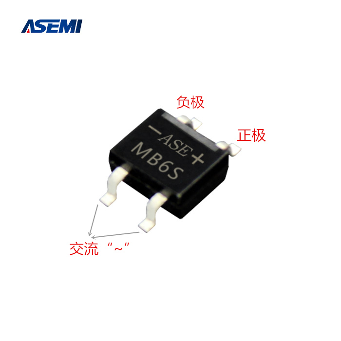
The SMD rectifier bridge is based on the MB6S commonly used by the ASEMI brand. As shown on the left, we can see the relationship between the positive and negative poles of the chip rectifier bridge and the positive and negative poles of the four pins. When wiring the chip rectifier bridge, we can refer to the positive and negative poles in the picture for proper wiring.
As can be seen from the figure, this patch bridge MB6S has four pins that are extended by the black plastic seal and bent at the end. This is to design the circuit board and also a series of stickers. The origin of the chip rectifier bridge naming. The four pins (leads) of the MB6S are located at the left and right ends of the body, and the vinyl glue in the ASEMI brand MB6S
02 wiring method of Square
The patch rectifier bridge described above is easy to judge with the positive and negative poles of the four pins. The DC output with the "+, -" symbol is connected to the circuit load at the back end, and the "~" symbol or the unsigned symbol. Both feet are for AC input,connect to AC power. There is also a kind of square bridge rectifier bridge wiring is relatively troublesome, now for everyone to explain: the four-pin rectifier bridge square bridge also has a positive and negative pole and two AC power input. However, it is different from the general rectifier bridge wiring method. When wiring, pay attention to which position should be connected, and it cannot be connected incorrectly.
03 two situcation of wiring
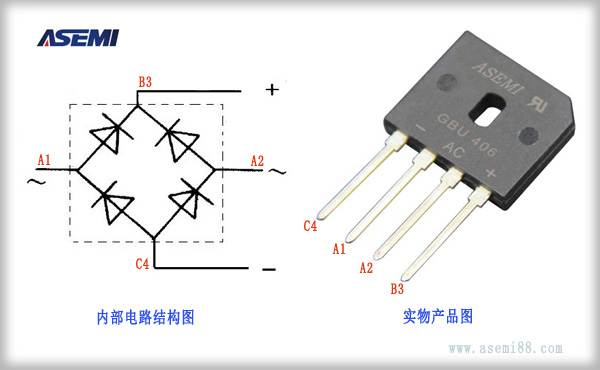
The rectifier bridge connection method is mainly understood in two cases, one is the corresponding way of the physical product and the circuit diagram. As shown in the figure: the left side is the internal structure diagram of the bridge rectifier circuit, B3 is used as the rectifier positive output, C4 is used as the rectifier negative output, A1 and A2 are used as the AC input terminal. The right side is the rectifier bridge physical product pattern, A1 and A2 Integrated in the middle position, the positive and negative poles are at the outermost side. In practice, we only need to connect the physical C4 negative pin to the C4 point of the connection circuit diagram, and the physical B3 positive pin to the circuit diagram B3. The appeal method is the connection method between the physical product of the rectifier bridge and the circuit schematic. The second way to connect the rectifier bridge is to connect the physical product in the circuit. Generally speaking, most of the circuits use high voltage rectification methods. Below we will focus on the circuit connection of the high voltage rectifier bridge. The front end of the rectifier bridge is an AC 220V input, enters the AC bridge of the rectifier bridge, and is connected to the positive pole of the load consumer by the positive DC output. The anode of the load is connected to the negative pole of the rectifier bridge to form a loop to complete the rectification path of the entire power supply.
The above is the introduction of the rectifier bridge method. Hope it’s helpful to you , thanks.
ASEMI TECH
will be better
END


 Hotline


